
I think part of what separates the pros from the kids in electrical engineering is circuit simulation. It takes much of guesswork out of circuit design and helped me greatly as I was starting out. But software like LTSpice have a steep learning curve. I wanted to reduce the learning curve, and this project is an attempt at that.
I wanted to make a machine learning model recognize electrical schematic symbols, so that a pen and paper drawing could be digitized. From there it is much easier to tweak the parameters and simulate the circuit. But first, I needed training data. And lots of it!
Failing to find a good dataset of schematic symbols, I ended up drawing hundreds (thousands?) of symbols by hand. I wrote a script using OpenCV in Python to grab individual symbols from pages of symbols and convert them into an MNIST dataset.

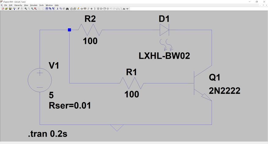
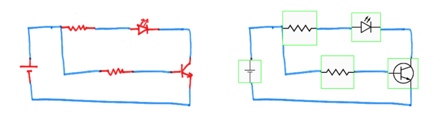
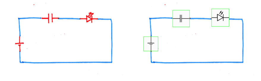
I created a vocabulary of 20 symbols and trained a model in tensorflow to recognize the symbols. I used Pillow in Python to replace them in the hand drawn schematics, taking into account position, rotation, and scale. Here are some of the results:
The next steps are to use the node positions of the symbols and run a maze solving algorithm (probably A*) to find connections between the symbols. I can then use a python spice library to convert the circuit into a spice model ready to be imported.
All the models and code is available on the project GitHub.

Amazing project man! I’m doing a very similar project and was looking for hand drawn symbol data and came across this 🙂
LikeLike
Thanks! Hope it helps you out. Would love to see your project so please think to share it xD
LikeLike