Wood burnishing roller – an attempt

For the final project I decided to make a roller that can burn a QR code on wood. It would be made out of 1″ aluminium stock with a heating rod inside. I would primarily use the 4axis mill.

First I had to generate the QR code, and because it had to be milled, I needed something with rounded corners. Thankfully I found unitag, a website that generates such QR codes easily. The website itself oly generates PNG images, and I needed vector images, so I used their API to generate the SVG. Here is the final QR code which links to my website:

Unitag_QRCode_1550790190904.png

I needed to project this QR code on a cylindrical surface and extrude it. After a bit of searching around, I found this tutorial which did almost what I needed, and I just changed the text to SVG image instead. I had to stretch the image about 10% in the y-axis to make the final curved image square.

Capture

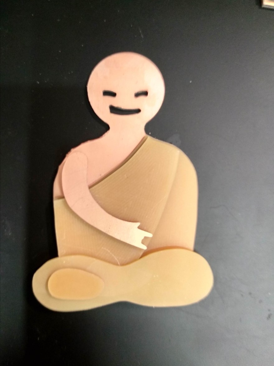
I 3D printed the file first, to make sure I had it right.

20150111_064409

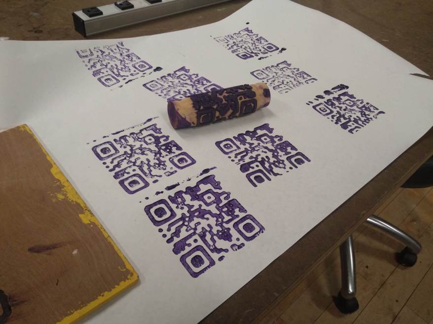
I then tried it on a wooden dowel to get the process right before milling aluminium.

Animated GIF

The result was a pretty nice ink roller.

img_20190309_000501

I finally started milling aluminium and after a few failed attempts with ball nose bits, I got it right with a 1/8″ square bit. I had to modify the 3D file a bit to increase the gaps, so i could do the entire process with a single 1/8″ square end bit.

Here’s the final piece milled

img_20190314_191203_957

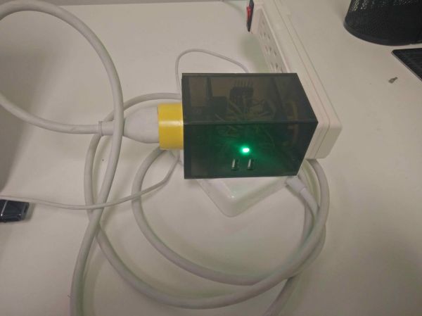
I’m adding the heating elements to make it a wood burner.

20150111_064518

METAL LATHE – I

This week, I decided to make an aluminum knob for a potentiometer.

img_20190214_231303-1

The process is pretty simple. I started by mounting a solid aluminum blank on the three jaw chuck. I faced the blank, turned it to a cylinder and then flipped it. Faced and turned the second end as well, and the blank was ready to shape.

I turned about 20mm length from the end down to 16mm to make a top hat kind of shape. Then I drilled a center hole on the tail end of the workpiece. I drilled a 6mm hole to accommodate the potentiometer.

I sanded the piece with sandpaper and scotch-brite. Then I cut it off with a hacksaw and mounted it on the lathe again to face and sand the bottom.

WOOD LATHE – II (getting to mallet)

For this week’s assignment, I made a mallet on the wood lathe.

img_20190217_151822

The first step was to glue up plywood pieces and make blanks. I used scrap plywood and as I’d soon find out, this was a very bad choice.

I started with the head of the mallet. The first step was to round the blanks. I used a round nose tool and sharpened it often. For the most part, the process went smoothly, but a few big chunks of wood did separate from the ply and hit the face mask. This is why you wear a face mask, people!! And this is also why we don’t use the cheapest ply on a lathe.

The stock was much larger than needed so I cut out a smaller piece with the parting tool. I shaped the work free hand.

The mallet head needs three holes, one to accept the handle and two smaller holes to accept pins which would retain the handle. The holes should be centered and that’s why we need this drill jig. I tried to make the jig out of plywood a few times, but a single plywood piece turned out to be too difficult to work. The tool tended to bite into it and stopped the piece from rotating. I tried cutting the piece beforehand to shape it roughly and reduce the material needing to be removed. But it would splinter at the chuck or just break at the tool. I finally used a small stock of soft pinewood instead.

With the the jig in place, I indexed the lathe and drilled the holes. For the handle, I chose 1.25″ spade bit.

The handle was shaped freehand out of plywood as well. I had to remove the handle from the lathe to check the fit to the head often. A few times the handle got removed from the lathe while turning. I think this was because I tightened the tail only before starting the lathe. When I started the lathe and used the tool, the torque would make the chuck bite into the wood more, and that would loosen the work at the tail. I had better results when I tightened the work one more time after starting the lathe and stopping it again.

After turning the handle, it was just a matter of gluing up the handle, drilling holes to hold the pins and gluing the pins in.

A quick buffing session later, the mallet is ready!


Wood Lathe – I

I love wood working, so I was very excited to get started with the lathe. But even for a first project, I think making a simple handle is a bit boring, so I decided to try adding an off axis step as well. Here’s a step by step guide of what I did-

I started with a soft wood dowel, marked it’s center and mounted it on the lathe. I used a round nose tool to shape the bulk of the handle, using my fist as a reference and free handing the design. I left the handle fatter than needed for now. And trued up the ends.


I then sanded down the sides at a ~5 degree angle on the sander and mounted it on the lathe in this angled configuration. I started the lathe at a slow speed and rounded the ends so that the weight wasn’t too unwieldy. Then I shaped the fat part of the handle, again using my fist as a reference.


When I was happy with the shape, I took the handle off again and mounted it in the original configuration for sanding. If I were to do this again, I would sand the handle in this tilted configuration before dismounting it. I sanded it with 60 grit and 220 grit paper.


I finished the handle with the wax buffing wheel. Here is the finished result-

Classifying resistors using KNN

For this week Azalea and I trained a KNN classifier to differentiate different types of resistors. We used a webcam microscope to capture images of resistors placed on a piece of paper as background. We trained the model with about 200 images of each type of resistor.

The results are shown in the video below. This model doesn’t seem to be the optimal approach to differentiate resistors. Perhaps a better approach would be to use this to differentiate between resistors and other electronic components and then read the pixel color values to decode the resistor value without machine learning.

Classifying resistors using KNN and MobileNET from tinkrmind on Vimeo.


Content: Activation Assignment

“An environmental awareness group loves your container and wants to use it to educate people about their new product, a takeout container made of plastic from algae – a totally carbon neutral option. They want the activation to be peaceful, calm, and approachable for the general public: informative, but not overwhelming.  They have a garant to find a way to distribute it (if only through documentation) to all homes in the US.”

A billboard made of transparent tubes stands in the middles of the park. The tubes are filled with a green fluid in a pattern which spells out a name or logo of a company. Every minute or so, the fluid moves and is replaced by fresh fluid, again in the same pattern. The accompanying sign reads:

These tubes are filled with algae which convert sunlight into hydrocarbons and make plastics. Press this button to purge the algae and see the plastic created by the algae so far.

Pressing the button removes all fluid from the tubes and the pattern stands out as a thicker layer of plastic tubing. As the installation continues, the tubes will get thicker and thicker eventually becoming solid.

Package Design

I was inspired by DigiKey and Mouser shipping labels. They contain a lot of information, some of it understandable, most of it not. It gave me space to play with the packaging while adding important information like my name and website.

img_20181010_111918_360

The label is designed in inkscape, printed and stuck to a DigiKey shipping packet.

Accessibility in Web Design- OpenROV Forum

For the accessibility assignment, I decided to look at the OpenROV forum. The project itself is large and multifaceted, but one would imagine that the forum, being relatively simple web design and meant for human interaction only (rather than attracting customers, say) should be accessible.

SiteImprove

Using the SiteImprove accessibility checker, I found that the user avatar images have titles instead of alt text describing the user. There were multiple instances of low contrast text as well. Link text was insufficient to determine where the link leads in many cases and aria-label was not provided for many links.

SiteImprove-OpenROV Forum

JAWS ScreenReader

Image titles were enough to describe images instead of alt-text. While aria-labels were provided for some buttons they were insufficient to describe the button out of context. The button for following a topic was not accessible via the screen reader and keyboard alone.

Some improvements that can be made immediately are increasing the contrast ratio on low contrast text, adding more descriptive links or adding aria-labels to the links, and making all buttons keyboard accessible.

Five shades of a PCB

I experimented with finishing techniques using PCB’s, Othermill CNC and some chemicals. The most promising colors are shown below:

img_20180926_032800_hdr.jpg  From the left they are: ferric chloride solution for 3 minutes, top layer milled off, original, tined, buffed. From here, I decided on a couple of color combinations and started fabricating.

img_20180926_033213_hdr1img_20180926_033610_hdr1 img_20180926_034203_hdr1

img_20180926_034049_hdr1

While none of them quite capture the aesthetic I’m going for, the last one warrants further exploration.

Bending PCBs

Prototyping Printed Circuit Boards(PCBs) is now cheaper and easier than ever before. We are seeing a huge increase in the number and quality of small batch custom boards, like DefCon badges.

In its simplest form, a two-layer PCB consists of three layers- a copper layer, a substrate like FR4, and another copper layer. The substrate is generally a lightweight, stiff material. High-quality PCBs have strong adhesion between the copper layer and the substrate.

milling-0


Desktop CNC’s allow milling PCB’s in-house. When milling your own PCB, an engraving bit is used to mill away the copper on the top to leave the insulating substrate, thus making electrical traces. A thick layer of the substrate is left to provide structural support, as shown below.


The substrate is quite stiff and does not allow bending at most temperatures(although, it has been done). But the copper is quite malleable. So if we mill away most of the substrate, a point bend can be made as shown below. The resulting cut in the PCB can be soldered to maintain the 3D shape as well as to keep electrical conductivity.


Note that this technique is very different from using flexible or semi-flexible PCBs. For one it is much easier to prototype and it results in rigid 3D structures.


Prior art:

Punk Monk- Exploring 2.5D Shapes

I started out exploring shapes afforded by bending PCB material. Specifically, I explored making Miura fold which might allow warped 3D shapes from a single piece, and making a semi-dodecahedral lamp.

After spending some time with the material and process I had a better idea of the possibilities, and it became clear that making the entire toy using this technique is unfeasible. So as a next step, I made 2.5D mock-ups of the final design in 2.5D by stacking paper, first hand-cut then designed and laser-cut.

Content and (dis-)contents: Assignment 1

Container: PCBs

Prototyping Printed Circuit Boards is now cheaper and easier than ever before. This is because of automation of the production process in a large-scale bringing down cost of manufacturing. And, the availability of free tools and tutorials to design circuit boards.


The container offers affordances in the form of layers of materials sandwiched together. The layers are silkscreen, solder mask, copper, FR4, copper, solder mask, silkscreen. From the perspective of a designer, the material offers more affordances than can be easily counted, so I shall focus on affordances to the user of a produced PCB. Here are some of the affordances and great examples of their use to create good content:

  • The copper layer affords passage of electricity. All the other layers provide the anti-affordance of blocking the flow of electricity. e.g. PCB motor
  • The copper layer provides the anti-affordance of blocking light from passing through, all the other layers provide the affordance of letting light pass through to varying degrees. e.g. PCB visual Art
  • The FR4 material provides the affordance of structural stiffness and temperature stability. e.g. PCB drone badgePCB enclosures
  • The copper layer affords to stick to solder and soldermask affords the anti-affordance of repelling solder. Together these afford sticking components on the board strongly and precisely. e.g. PCB Braille signs

Response to in-class questions:

What is content? What makes “good content”? What makes “viral content”? How are they the same and how aren’t they?:
Good content satisfies needs, viral contents satisfies wants.

How is it useful or detrimental to think in terms of content/container? Is there another way?:

Container/content model separates the users from the designers i.e. designers make the container, users use the container to make content. Granted there is often overlap in the people acting as designers and users i.e. a person can be both a user and a designer. Nevertheless, there is seldom an overlap in the thought process of acting as a designer/user i.e. a person seldom acts as both at the same time or in the same mindset. So the divide is valuable. At the same time, I feel like better design emerges from a narrow divide between designer and user, and both should inform and influence each other.

Can the same “content” be translated across different containers?:
Yes, definitely! For example, a painting can be made in any medium, a piece of music can be played with many instruments, The same spice/texture palette can emerge from different ingredients. But also, synesthetic nature of humans means that similar emotions can emerge from different sensory inputs.

Can the same “content” be translated across different containers?:
I put container first, more often than not. In fact, I see the world in terms of simple components e.g. I see a toaster as a heater connected to a timer rather than a means of generating toast(the content). My process is to explore the perceived affordances of a container, drill down to the real affordances and think of which affordances are invisible. Then, make them visible! For example, the copper layer of a PCB affords bending, but this is seldom visible because the FR4 layer affords stiffness. I am currently exploring making bent PCBs to surface this previously less visible affordance.

Can the same “content” be translated across different containers?:
Yes, users deserve compensation from the content they create. Even if it is non-monetary compensation in the form of reputation/credits..


Reflections on the reading:

Two forms of bad writing that I hate are (a) jargon-heavy text with runaway sentences (b) writing that makes universal claims without citation or context. The reading Rethinking Affordance- An Introduction seems to combine the two into a perfect mix of misery. After reading the piece three times I still don’t understand what the author wants to convey other than that they think that ‘affordance’ needs to be redefined for the digital age. I have more issues with the text than can be easily listed, so I shall not attempt to list them.

Hello Git- Open Source Studio

I have worked as an engineer for a few years now. And since the very beginning git was part of the workflow. I started out by pushing back. I forced people to send me zipped files and did the version control myself. This works for small projects but it’s terrible for maintaining anything larger than a text file.

I reluctantly accepted git and GitHub; slowly. I started out learning git for maintaining personal projects, with low stakes. I maintained my CV in git, maintained a few Arduino codes here and there. No big deal. For the most part, git was just a way back machine rather than and serious version control. No fancy branching or issue tracking, just a backup for old code, in case I need to get back to it. When my laptop was stolen I doubled down on using GitHub for backup. I now have well over 50 repos, most of them horribly maintained spaghetti code with the last commit made a year ago. They’re not meant for collaboration.

I’ve made a few blunders while using git. I’ve published IP protected code publicly without a license. I’ve had ‘detached head’ errors and ‘merge conflicts’ and while fixing them I almost destroyed repos. But I’ve learned a few lessons from all this. Here’s what I’d tell my past self:

  • It takes less time to learn git than to do manual version control
  • Don’t be ashamed to publish your code. No one’s gonna read it anyway.
  • You can’t push and pull too often
  • When in doubt don’t just read a forum post and use the -f flag. Talk to an expert or think about it.
  • There’s no shame in using a GUI to interact with git. GitKraken is beautiful!

I’m still learning and I’m still making mistakes that seem ridiculous with hindsight. But I’m happy that they’re at least public.

Reflections on readings:

I connected to the message of inclusiveness in multiple readings. Whether it be by simply being polite to n00bs or going out of your way to include diverse groups often at cost to the project. I think more transparency and diversity leads to better projects. That said, the old adage ‘A committee should consist of three men, two of whom are absent.’ also springs to mind. We should be aware that inclusivity comes at the cost of overheads and slower decision making. We should not be quick to forget the fruits reaped by grace of the BDFL’s.

Personally, I will be more mindful and sensitive towards feelings of anonymous people on forums. And practice polite discourse or refrain from commenting.

Laptop battery savior

I use my laptop mainly in the office so generally it would be connected to the charger all of the time. WIRED seems to think that this will kill my battery and that I should instead cycle between 80% and 40% capacity. Very well, I can’t change my habits but I sure can make stuff to have the same effect.

This project is a Bluetooth relay controlled by my laptop. I plug in the laptop charger into the output of the relay. A bash script monitors my laptop charge in the background and switches the relay on and off to maintain the mythical 80-40% charge level. I’m not fully sold on the idea of cycling the battery vs fully charging it. I’d love to hear from someone who knows their Li-ion battery chemistry.

I published a step-by-step tutorial for this, including the CAD files and all of the code. It got featured at Instructables.

laptop-battery-saviour
DIY Bluetooth relay controlled by my laptop.


Yupo Jelly – it sucks!(and that’s good)

Yupo Jelly is a transparent PET sheet with micro-suction cups on the back that stick to flat surfaces. Since it works using suction, it doesn’t leave any adhesive residue when removed.

It is typically used for putting up signage temporarily. It does not support printing via inkjet or laser printers however and needs one of the following techniques: UV offset, UV silkscreen and UV digital. It is fully recyclable.


IMG_20180320_162717.jpg
A ruler is dangling on the side, being stuck to the yupo jelly paper.

Material ConneXion Link

Manufacturer Link : The manufacturer is easy to get in touch with and eager to work with artists. Samples are provided freely. Product is available for purchase from the manufacturer easily. Swatches available through application here. Distributors.

Product Datasheet1 / Product Datasheet2

Interesting use cases:

  • Laptop webcam cover
  • Put it all around your house: mount your phone on the walls
  • Holding down mylar or similar light material while laser-cutting
  • Holding PCBs for SMD assembly

Custom fit silicone glove(with embedded electronics)

Process

3D scanning:

I scanned my hand using iPad structure sensor. The sensor had a lot of trouble scanning my hand separate from my body, so I set up a board with a hole to scan my hand as an object instead. Many thanks to Ridwan for helping me with the scan.


3D modeling:

A 3D model produced was processed and reduced in meshmixer. The resulting model is uploaded to sketchfab here. I want to try out wrapX for redefining the mesh.

I then made a shell around the model and split it in two. I had to be careful to split it such the two halves could fit on the model when 3d printed. The separation between the model and the shell is 2.5 mm(1/8″) this is so that I can use 2.5mm(1/8″) acrylic pieces as spacers to ensure the model is centered inside the shell then closed.

3D Printing:

I printed the models using Cura and Ultimaker 2+. Since the model is relatively smooth, the layer height does not need to be fine. Even a 4mm layer height with 6mm nozzle is good. There were a LOT of failed prints.


Take care of the orientation of the build. It can have a huge effect on the time taken for the print.

Polishing:

The print needs to be cleaned up before use. I sanded the prints with a Dremel, going slow to prevent melting. Then I covered the entire surface with epoxy. The epoxy adheres to the rough surface well and allows the silicone to be removed easily.


Adding electronics:

I stuck discs of 2.5mm(1/8″) acrylic on the model, spaced regularly and test fitted the shell. Then I stuck neopixels and a flex sensor on the model. I used silicone wires to connect the sensors so that it sticks to the poured silicone easily.

Casting:

I followed standard techniques to cast silicone using a vacuum chamber. I’d recommend this video for instructions.

What went wrong:

The silicone I used(EcoFlex-30) has a relatively low working time of ~20 minutes. So there wasn’t enough time to degas the silicone when pouring it into the thin cavity between the model and the shell. The bubbles got trapped in the silicone and ended up in the final solid cast. Also, the silicone is not very durable and tears easily. And the electronics are not flexible enough to allow the cast to be removed from the model without damage.


What I would do differently:

  • Model in a different way so that the casting is in a perpendicular direction. Having a shorter distance for the bubbles to travel will allow for easier casting.
  • Design the mold with air escape holes at the bottom
  • I would use silicone with longer working time.
  • Use shorter stretches of electronics separated by coiled silicone wire.

Bio-inspiration in soft robotics

Fig wasps and figs trees live in a mutualism ecosystem where the fig tree provides nourishment to wasp eggs and the wasps pollinate fig flowers. This is a mutually beneficial arrangement. The lifecycle of a fig wasp is illustrated below.

Selection_008
Life cycle of a fig wasp

So, female wasps pollinate the fig flowers by entering the fig with their pollen laden body. Parasitic wasps have co-evolved to get nourishment from the fig trees without pollinating the flowers. They do this by drilling into the fig from the outside with their long ovipositor.

From an engineering perspective, the ovipositor is a flexible, maneuverable hollow tube with sensing elements at the end. This mechanism has been studied by multiple researchers with recent findings experimentally studying the mechanisms of insertion. The tip of the ovipositor is enriched with zinc, presumably for hardening.

image_1951-Parasitoid-wasp
A parasitic wasp drilling into a fig. Photo credits: Lakshminath Kundanati.

This problem can have interesting direct applications in any number of in vivo experiments e.g. in neuroscience for non-destructive probing of brain cells.

Novel experiments in cable mechanisms

Cable mechanisms consist of a tension(/compression) bearing cable running through a compression(/tension) bearing channel. This mechanism can be used to transmit force over relatively long distances with light and flexible material. Notable examples include Bowden type 3D printer extruders, bicycle brakes, early car throttles etc.

While experimenting with sphincter type channels, I discovered that to get symmetric contraction of the mechanism it is important to apply force through both ends of the cable as shown below.


I used this mechanism to make Cookie Monster, an evil cookie jar that doesn’t let you take cookies. If you reach in and grab a cookie, it mouth of the jar traps your hand and won’t let go until you drop the cookie back in the jar.

[DEMO]

I want to make a robust version of it, keep a delicious cookie or amazing toy inside and exhibit it in a children’s museum. I can just imagine kids trying all sorts of ways to get at the toy and failing. Ahhh.. it’ll be fun to watch that! If you’re someone who can make this happen, I want to get in touch with you!

I also experimented with developing a lightweight upper body exoskeleton to help me do pull-ups. But I gave up on the idea when I realized that a robust mechanism would require at least some metal machining. If you want to develop the concept further, feel free to reach out. I’d be happy to share thoughts and experience.

videotogif_2018.01.29_04.53.33.gif

Sez – A wearable prototyping platform

Most of the effort in making a wearable electronics project seems to go into the mechanical sewing of conductive thread and placement of components. This does not leave enough room for exploration, say changing the placement of components or trying out different ones. This seems reminiscent of early rat-nest electronics prototyping before breadboards came along.

The aim of this project is to make a wearable jacket with pop-in connectors that act as a bridge between the clothing and Arduino pins. The jacket will essentially be a breakout board for Arduino pins on to the body. This way wearables can be prototyped quickly. To further ease the development, the jacket will have wireless connectivity, and power management built-in.

Some projects that can be easily built using this setup are:

  • Animated name-tag
  • Music synth touch controls and wearable speaker
  • Bike turn lights with touch controls
  • Posture tracker
  • Personal space tracker
  • Hands-on multimeter/conductivity tester (I’m most excited about this one!
  • Gesture based remote control

Ideation:

The project has evolved over the past two months through the Wearables class at Tandon, NYU (DM-GY 9103-I). It started out as a wearable breadboard, with the aim to allow quick and dirty wearable prototyping. After much design and redesign, I realized that a robust and easy to use solution is not possible. So I altered the idea to be a wearable prototyping platform.

I wanted the jacket itself to be very robust against wear and tear, even with rough use. So I opted against sewing conductive thread. I researched a lot for a suitable conductive material, testing dozens of metal ribbons. I finally settled on steel ribbon from Adafruit. But the ribbon is prohibitively expensive at 25$ per meter. In true ITP fashion, I hit the junk shelf instead and realized that the steel sheathing for display cables is an ideal replacement. I stripped around 10 meters of the stuff and was on my way to fabrication.

Fabrication:

I designed the PCBs in KiCAD and then manufactured them with an OtherMill. The jacket was purchased and the female snaps added by hammering in place. Steel mesh cables were added with insulated covers and a layer of lining was added for comfort.

Next Steps:

I’m looking for collaborators to make projects with Sez. I’d love to hear from you if you’re interested!

Designing a Business Card

As a first step to designing a business card, I made a map of adjectives that best describe me. Here is the mind map that resulted:

map

The common theme that is relevant to a business card is my self-identification as a maker. Since I have a broad set of skills in electronics, carpentry, design.. a title such as creative technologist seems too constrictive. So I decided early on not to include any title.

I looked through my desk drawer for business cards and found a few samples to draw inspiration from. I particularly liked the simplicity of ny sci business cards. The portrait orientation makes it stand out and the watermarks give a pleasant second read without being too distracting on the first read. Inspired by this, I decided to adopt a portrait orientation and watermarks suggesting my skills. I got a lot of icons for tools, electronics, art and code to use as watermarks from The Noun Project.


fontSelection
I experimented with a lot of styles and combinations on my name and handle (tinkrmind) on paper, before looking for fonts online. I decided to go with ‘Sawasdee’ for the contact information. It is a compact font, which renders will for the portrait orientation. The fact that it is open source is just a cherry on top. For my handle and name I decided to go with ‘Neon 80s’. It is a playful and bold font in contrast to ‘Sawasdee’.


I wanted to develop a logo for my handle as a part of this project. I wanted the logo to represent both art and tech. I made the following two logos. I finally decided to go with the cog and brain logo since I think that the wrench and paintbrush look too much like a construction company logo.


Since I generally rely heaving on grids, I took it as a challenge to work without a grid and go with intuition composing this project. I settled on a fairly simple design, with a symmetrial composition for the back.


Colors

Experimenting with changing color palette of an image:

The technique: I converted the image into 5 color palette using the imageMode tool in GIMP(~photoshop) and the used the alien filter to change the palette until I found something interesting.

I used these colors as an inspiration to get the palette below.

Selection_004

I made the following compositions with this palette in Processing – original image files and source code on github:

I really enjoyed changing the palette of the leaf image above, so I made a tool in p5.js to convert any image into my palette. (code on github and alpha editor) Here are some interesting compositions that resulted from playing around with this code: