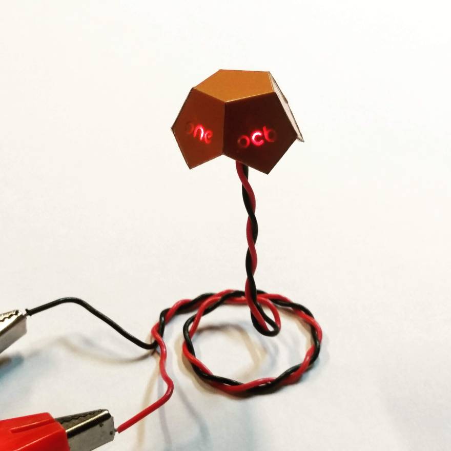
Prototyping Printed Circuit Boards(PCBs) is now cheaper and easier than ever before. We are seeing a huge increase in the number and quality of small batch custom boards, like DefCon badges.
In its simplest form, a two-layer PCB consists of three layers- a copper layer, a substrate like FR4, and another copper layer. The substrate is generally a lightweight, stiff material. High-quality PCBs have strong adhesion between the copper layer and the substrate.

Desktop CNC’s allow milling PCB’s in-house. When milling your own PCB, an engraving bit is used to mill away the copper on the top to leave the insulating substrate, thus making electrical traces. A thick layer of the substrate is left to provide structural support, as shown below.
The substrate is quite stiff and does not allow bending at most temperatures(although, it has been done). But the copper is quite malleable. So if we mill away most of the substrate, a point bend can be made as shown below. The resulting cut in the PCB can be soldered to maintain the 3D shape as well as to keep electrical conductivity.
Note that this technique is very different from using flexible or semi-flexible PCBs. For one it is much easier to prototype and it results in rigid 3D structures.
Prior art:
- PCB enclosures
- Multiple products that use PCB’s as structural elements like eggbot, PCB drones


