PunkMonk final design is ready!


Makes stuff.
PunkMonk final design is ready!
I was inspired by DigiKey and Mouser shipping labels. They contain a lot of information, some of it understandable, most of it not. It gave me space to play with the packaging while adding important information like my name and website.
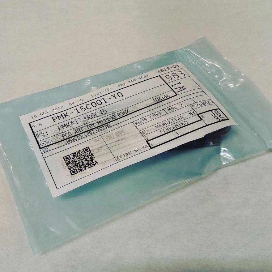
The label is designed in inkscape, printed and stuck to a DigiKey shipping packet.
This week I experimented with some more techniques to color and attach PCB’s.


I experimented with finishing techniques using PCB’s, Othermill CNC and some chemicals. The most promising colors are shown below:
 From the left they are: ferric chloride solution for 3 minutes, top layer milled off, original, tined, buffed. From here, I decided on a couple of color combinations and started fabricating.


While none of them quite capture the aesthetic I’m going for, the last one warrants further exploration.
Prototyping Printed Circuit Boards(PCBs) is now cheaper and easier than ever before. We are seeing a huge increase in the number and quality of small batch custom boards, like DefCon badges.
In its simplest form, a two-layer PCB consists of three layers- a copper layer, a substrate like FR4, and another copper layer. The substrate is generally a lightweight, stiff material. High-quality PCBs have strong adhesion between the copper layer and the substrate.

Desktop CNC’s allow milling PCB’s in-house. When milling your own PCB, an engraving bit is used to mill away the copper on the top to leave the insulating substrate, thus making electrical traces. A thick layer of the substrate is left to provide structural support, as shown below.


The substrate is quite stiff and does not allow bending at most temperatures(although, it has been done). But the copper is quite malleable. So if we mill away most of the substrate, a point bend can be made as shown below. The resulting cut in the PCB can be soldered to maintain the 3D shape as well as to keep electrical conductivity.


Note that this technique is very different from using flexible or semi-flexible PCBs. For one it is much easier to prototype and it results in rigid 3D structures.


Prior art:
I started out exploring shapes afforded by bending PCB material. Specifically, I explored making Miura fold which might allow warped 3D shapes from a single piece, and making a semi-dodecahedral lamp.


After spending some time with the material and process I had a better idea of the possibilities, and it became clear that making the entire toy using this technique is unfeasible. So as a next step, I made 2.5D mock-ups of the final design in 2.5D by stacking paper, first hand-cut then designed and laser-cut.


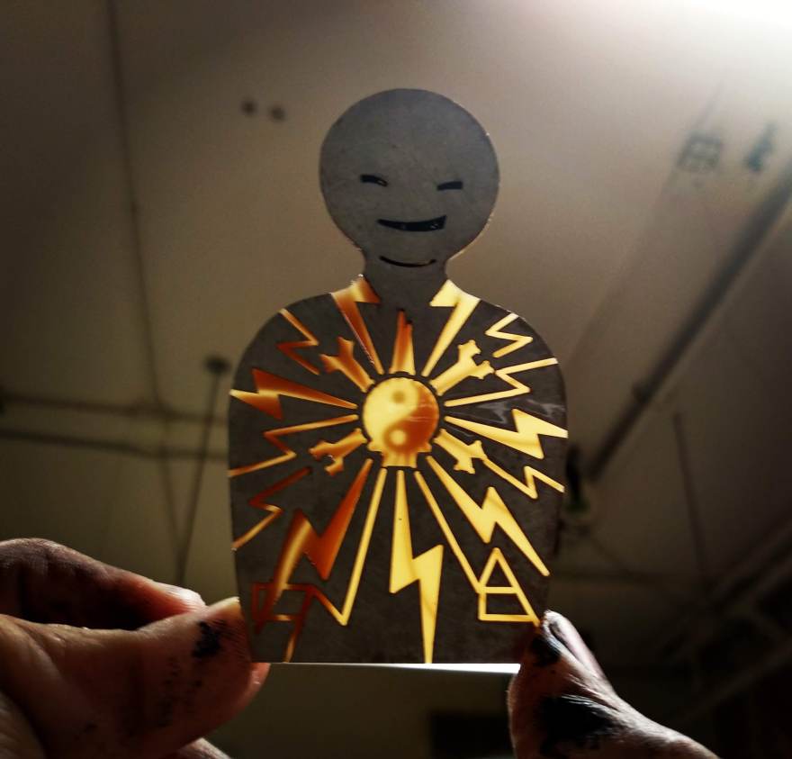
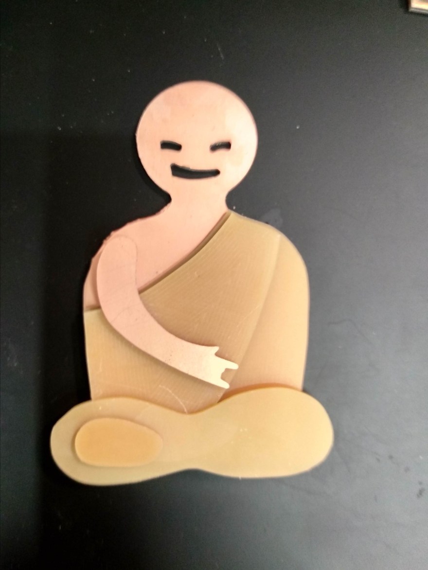
The character was inspired by an MP Tourism Ad. Punk Monk is a monk wearing headphones and nodding to a beat. A lot of work went into getting the expression on the face right. I experimented with various facial features and settled on the simplest look with just eyes and a smirk.


Construction:
The first model is a bobblehead with headphones made out of milled PCB. The wooden model and PCB are separate pieces held together by friction fit.
The wooden model was made out of two wooden dolls. The first one had its head turned down on a lathe to leave a holder for the spring on which the head will rest. A long hole was drilled along the length of the body to pass two wires from the base to the head. The wires act as + and – leads to the LED’s on the headphones.


The head was made by separating the head from another doll. It was drilled down to have a hole in which to rest the spring and a wider hole to allow free movement. Two thumbtacks were pushed into the head where the ears would be and thin copper wires were attached to the tacks to act as electrical connections for the headphones.


The PCB headphones were made out of doubled sided FR4 PCB. They were modeled in OnShape, keeping PCB thickness and size of the wooden head in mind. The PCB material itself is not flexible, but the copper layer on the end is. So at a point of bend, the FR4 material is milled away to leave a thin copper layer, this creates a sharp curve, and the appearance on the outside is that of a continuous copper layer with no breaks. A jig was made to place the PCB in the right shape and soldered on the inside to have it retain the shape. The ear cushions were made by gluing another octagon of PCB material.


Electrically, the PCB has two wires running along the inside length. They are for the + and – pins of the LEDs on either earcup. The LEDs are in parallel. The ear cushions act as the electrical contact to the head through the thumbtacks and are electrically connected to the + and – pins on either end. The leads run down the length of the doll and to an Arduino and battery which pulsate the LEDs.


The base is made of MDF with a hole to hold the doll and another, larger hole to hold the arduino and battery.
The entire model was painted with acrylic paints.
